Oct 2014 Newsletter - Transmissions Vol 14, 2014
 Vol. 14, 2014
Transitions
 It is with a mix of pleasure and sadness that we wish our Gear Research Institute, Managing Director and Chief Operating Officer, Suren Rao, PhD, a ‘Bon Voyage’ as he heads into retirement after a long and notable career in manufacturing and research.
Dr. Rao began his technical education at the University of Bangalore, and began working life at the Central Machine Tool Institute of India. It is here that he became interested in research which led him to seek post graduate education. He developed an early interest in academe during teaching assignments at University of Wisconsin and at McMaster University in pursuit of his ME and PhD degrees in Mechanical Engineering. His first post-doctoral assignment was at Battelle Labs in Columbus Ohio, as a research scientist in metal working. Next came a tour in the manufacturing world, and for the next seven years at National Broach and Machine Company Dr. Rao progressed through many aspects of the Machine Tool business beginning as Director of Development, and completing his assignment as VP of Engineering.
In 1990 Dr. Rao moved to Washington DC, and joined the National Science Foundation on a temporary assignment. It is here, which fortunately for us, he came in contact with Penn State and in 1993 landed in the “Happy Valley”. It was there in State College that he and his wife raised their three lovely daughters over the next twenty plus years. This is also where he further distinguished himself in the power transmission world, beginning as Senior Scientist at the Applied Research Lab’s Drive Train Technology Center. He was able to continue his interest in developing the next generation of engineers as an Affiliate Professor in PSU’s department of Industrial and Manufacturing Engineering.
But for those of us in the Gear business, it was Rao’s role as the principle factor and facilitator, in the AGMA and ASME’s decision to move the Gear Research Institute (GRI) from Chicago to Penn State in 1996. His hard work and leadership has been the main impetus in the development of GRI as a leader in private and pre-competitive gear research.
Luckily for us at GRI, Suren is not rushing off immediately. He has agreed to work a somewhat less rigorous schedule to help transition his successor Aaron Isaacson, who we will introduce you to in our next edition of Transmissions.
Please join us in wishing Suren the very best in the next phase of what, has been a most outstanding career at This email address is being protected from spambots. You need JavaScript enabled to view it..
Sincerely,
Sam R. Haines
President
Chairman CEO, Gear Motions Inc.
www.gearresearch.org
Research Projects
A review of several issues of this newsletter revealed that while most other gear testing methods had been discussed in some detail, very little specifics about the humble rolling/sliding contact fatigue (RCF) test has been presented. A picture of the equipment utilized in this experiment is shown in figure 1 and a schematic of the set-up is illustrated in figure 2.
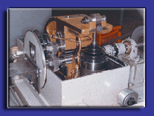
Figure 1: RCF Test Machine
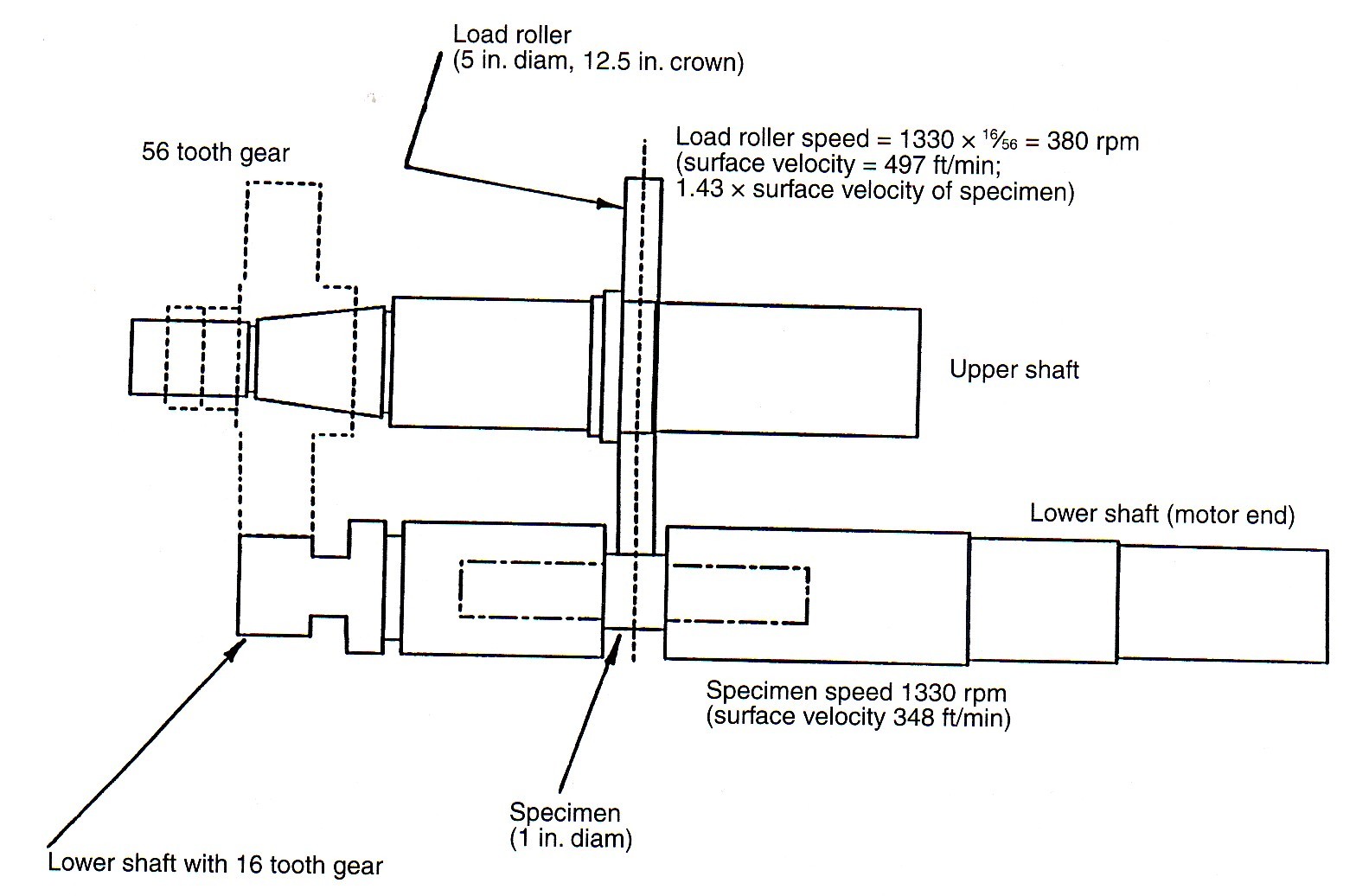
Figure 2: RCF Schematic
As can be seen from Figure 1, the load roller is mounted in a swing-arm assembly that is pulled down to create the contact pressure between the load roller and test specimen at the contact surface. The rotational speed of the test specimen can be 1300 rpm or 3000 rpm, depending on the pulley combination utilized. An infinitely variable speed option on the RCF test machine is being pursued.
The schematic illustrates that the test consists of a load roller resting on a cylindrical test specimen. The test specimen is driven by a motor and the load roller rides on the test specimen. A gear ratio between the two provides the sliding. This rolling and sliding combination approximately simulates the processes occurring at the flank of a gear tooth. This test is primarily intended to evaluate the resistance of candidate material systems to surface origin pitting; however, other modes of surface failure can be studied. The surfaces of the specimen and load roller are sliding against each other, with lubrication, under high load. Therefore, some indication of the lubricated wear resistance of the material being tested can be obtained; also the resistance of the material/surface finish/lubricant system to scuffing can be studied.
While the RCF test simulates the conditions occurring on the gear tooth flank under load, significant information on the load bearing characteristics of materials can be derived from this test at a fraction of the cost of fabricating and testing gears. However, this is always presented as a “screening” test, especially when a large variety of materials or other variables are to be evaluated. The RCF test is an invaluable tool for narrowing the field of material and variables and actual gear testing and evaluation can be conducted only on those materials that excel in performance in this test.
Altering the gear ratio between the load roller and test specimen spindles while maintaining the center distance can vary the amount of sliding in the test. Typical ratios are 21% and 43%. Tests are conducted at very high overload to promote failure in “real time,” thus; it is possible to introduce plastic deformation (rippling) on the contact surface. With specially adapted equipment, these tests can also be conducted at different temperatures up to 400ºF. Specimens and load rollers can be designed for a variety of testing requirements, depending on the exact material and objective of the test.
The lubricant stream to the specimen/load roller interface is aimed at the discharge side of the mesh (to cool the surfaces after contact). The lubricant flow rate is adjusted to two liters per minute (or as specified for the project), with lubricant at test temperature. Alignment of the specimen and load roller is checked, as each test is set-up to ensure that contact occurs uniformly at the center of the load roller. Before the start of testing at load, a break-in run is typically conducted. This is accomplished by running the machine ten minutes at each of a series of increasing loads up to the full test load.
Tests are stopped periodically, and the contacting surfaces of the specimen and load roller are inspected for signs of surface distress. The diameter at the center of the specimen is also measured to provide an indication of wear. The formation of large, progressing, pits produces a strong vibration signal, which, in turn, shuts down the test. Lubricant temperature, lubricant pressure, and air pressure (to apply the contact load) are also monitored, and the test is stopped if irregularities are detected.
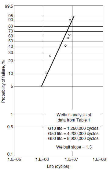
Figure 3: Weibull Analysis of RCF Data
The results of contact fatigue tests exhibit more scatter than is typical with other fatigue tests and a Weibull analysis is an essential tool in interpreting the data. One gauge of scatter is the Weibull slope, a measure of the increase in rate of failure with increasing life. For many fatigue tests a Weibull slope of six or more is typical which implies that in a test of 20 identical samples tested to failure, the longest test would last about twice as long as the shortest. For contact fatigue testing with current ultra clean steels, a Weibull slope of 1.5 is typical. In the example noted above, if the Weibull slope were 1.5, the longest of the twenty tests would last about twenty times as long as the shortest. The impact of this on test programs is that many tests have to be conducted to develop enough data to make statistically meaningful comparisons. A typical Weibull analysis plot for a set of RCF tests is illustrated in figure 3. Comparisons between variants are made on either a G10 life or a G50 life basis.
In addition to specimen identification, load, and life to failure, other information is required to aid interpretation of results. These include lubricant, lubricant bulk temperature, nominal filter size, test speed, and phasing gear set (slide ratio). Also reported for each test is data regarding surface roughness, ratio of elasto-hydrodynamic lubricant film thickness to composite roughness, wear and wear rate.
Education and Training
In order to assist the gear industry augment its aging work force, the Gear Research Institute has DEVELOPED two initiatives to train more gear knowledgeable engineers at the undergraduate and graduate levels. This involves incorporating engineering undergraduate students, at the junior/senior level and graduate students in the Institute’s research LABS while being paid by a grant from the sponsoring industrial entity. Summer internships have also been arranged at the sponsor’s facility are also a part of the deal, so that the student and the sponsor have an opportunity to assess each other with future employment in mind.
 We had our first graduate of this program in the spring of 2013, who then joined John Deere at their Coffeyville, KS facility. We had a second student selected by John Deere, Byron Stuart, who graduated this spring and joined John Deere at their Waterloo, Iowa facility in August. Byron graduated with his B.S. degree in Biological Engineering specializing with the Machinery option and a minor in Off Road Equipment. This program appears to be working for this large manufacturer of agricultural equipment as this grant was continued by John Deere for the third year and another senior, who might be employed by them, will be joining shortly.
Typically, students get hands on experience by setting up and monitoring gear test equipment with additional training topics such as gear metrology, failure analysis, metallurgical characterization, vibration monitoring for failure detection, statistical analysis of test data and more.
For more information about how you can support a student intern please log in to www.gearresearch.org or contact Aaron Isaacson at 814 865 5832 or This email address is being protected from spambots. You need JavaScript enabled to view it..
The Gear Research Institute is a non profit corporation. It has contracted with the Applied Research Laboratory of The Pennsylvania State University to conduct its activities, as a sponsor within the Drivetrain Technology Center. The Gear Research Institute is equipped with extensive research capabilities. These include rolling contact fatigue (RCF) testers for low- and high-temperature roller testing, power circulating (PC) gear testers for parallel axis gears with a 4-inch center distance (testers can be modified to accommodate other center distances), single tooth fatigue (STF) testers for spur, helical and spiral bevel gears, and gear tooth impact tester. Extensive metallurgical characterization facilities are also available at Penn State in support of the Gear Research Institute. For further details on our testing capabilities please go to www.gearresearch.org or call Aaron Isaacson, Managing Director, at (814) 865-5832..